Today i want to share a new digital meter which have multi option of measuring, by using this panel meter we can measure the voltage, ampere and frequency hertz and we dont need to wire extra
voltmeter ammeter. We can also called this meter a advance type of panel meter. I also shown this meter images and its wiring diagram which is provided by company which i taken with my mobile camera. However the company diagram is not too hard and not completed thats why i design a diagram about this.
How to wire a voltmeter ammeter and frequency meter with current transformer CT coil?
The wiring of this panel meter is too simple, i want to show you an image of the this meter which is below.
 |
| Voltage Ampere Hertz meter |
Now lets see the company diagram which is provided by company, the below is company diagram, you can also find out digital meter usage and auxiliary power supply table.
 |
| digital meter company data and diagram |
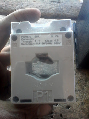
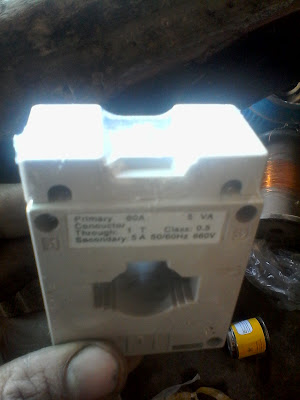
We also wire current transformer (CT coil) with this for measuring ampere or load, you can see the current transformer below. |
| CT Coil |
 |
| C T |
Wiring diagram of Volt-Hz-Ampere meter with Current transformer (CT).
Now after images, and panel meter company diagram, i am gonna to share with you a a complete wiring diagram of this meter which i design himself for this type of multi panel meter. In this diagram i shown that how to wire a current transformer (CT) with digital meter, how to wire a digital voltmeter for 2 phase 440 V measuring OR we can said that this is for 3 phase. and i also wire Hz frequenc y meter. Note that frequency meter wiring is done internally from company and you have to do wring as i shown below panel meter wiring diagram. In the below diagram i connect the single phase supply to the meter for display and then i get a connection for L1 (phase 1) and connect with input supply of 400 to 500 volts terminals. Then i connect the L2 to to input terminals of 2 phases(note that the we do not use meddle terminal of between to phases. After that i connect the CT coil ( current transformer) with meter.
 |
| multi function panel meter diagram |
I hope after viewing
voltmeter ammeter, hz meter wiring diagram, you will completely understood, now i you have any question regarding this post the you can ask me in below comments section below. IN
SHA ALLAH soon we will publish more digital voltmeter ammeter diagram which easy to understand.


Komentar
Posting Komentar