Postingan

Menampilkan postingan dari April, 2017

8 Refrigerator Not Cooling Problems and Its Solution Repair

Gambar
As refrigerator mechanic," mostly people ask me that her refrigerator not cooling and they take me to his/her home to check refrigerators, There are some main reason and problems of fridge and freezer not working and in this post i am writing about refrigerator not cooling problems and its solution. 8 Refrigerator not Cooling Problems And Its Solution / Repair Test the electrical outlet Mostly refrigerator stop working and stop cooling due to outlets where we get supply for refrigerator. In simple words every one know that refrigerator works on electric energy and if electric supply is not receiving to the fridge then how can it work. In this problem when we try to start the refrigerator and Ref not starting. The short and simple way to test the outlet voltage, plug in refrigerator shoe  and then check the lamp of refrigerator. If the lamp is glowing then there is no internal problem in electrical outlet and if its not glowing then test the outlet incoming current using multi

Tips To Fax Washing Machine Not Spinning Problems

Gambar
Washing machine numbering is those electrical appliances which we use very much in our homes. Today we disuse washing machine not spinning problems and how to fix and repair these problems. In this post we will lighting about these problems and its faxing methods. There are many problems of washing machine not spinning which we can face in our new or old washing machine, As we told you in above sentences that in this post we are lighting some tips about washer not spinning. In Below i highlight some reasons but IN SHA ALLAH we will make more helpful t utorials further on this site. 8 Big Problems of Washer / Washing Machine Not Spinning Low Or Wrong Voltage Problem The electric motor works on electric energy and its want some required pressure of voltage to work properly, if providing voltage is low then its will not working. For this, test your voltage and if voltage is low then use a voltage regulator to fix the voltage or take supply form other places. This is one of the big pro

Trailer Light Wiring Diagram 4 Pin 7 Pin Plug

Gambar
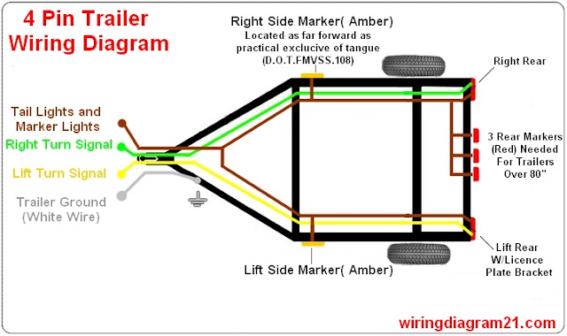
This article shows wiring diagram for trailer light plug 4 ,7 pin connector and step how to wire a trailer harness with color code ,there are some intricacies involved in wiring a trailer. Some trailers come with different connectors for cars and some have different wiring styles. If you follow our trailer wiring diagrams, you will get it right. Some connectors are 4-pin while some are 7-pin. 4 pin trailer light wiring diagram : 4-Pin Connectors 4-pin connectors are the standard used for most trailers. Many trailers have three circuits. The circuits are for left and right brake lights and running lights. Three wires are for the trailer while the last wire is the ground wire. The ground wire should be run from the frame of the vehicle to the trailer. There must be a very consistent metal to metal contact for the ground wire. So, do not run the wire from the bumper or the hitch of the car. The 4-pin standard flat style connector has four contacts wit h a male pin on the vehicle side f

How To Wire A 66 Block

Gambar
A 66 wiring block is an older but still widely used style telephone distribution panel. It is used to distribute incoming phone lines to all the phone jacks in your home. It may seem a bit confusing but well break down the parts so you can learn to wire a 66 block yourself. If you dont have a 110 block you may have a 66 block in your home. Phone companies can charge a monthly inside wire maintenance fee if you want them to repair any issues that may occur with the phone wires inside your home. If you learn to maintain your own phone system you can save a decent amount of money. For me its about $120 every year. 66 Block Components There are different types of 66 blocks. The most commonly used is the 50 pair Split 66 Block. The 66 block is normally mounted on an 89D Mounting Bracket to provide some clearance to run cables behind the 66 block. Pins in the center of the block are were wires get connected. On a split 66 block there are 4 pins on each row. The first 2 pins on a row are e

Complete Ohms Law Explanation Guide With Example

Gambar
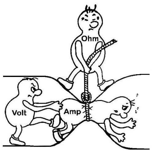
When an electrical student start his study or he select the electrical technology that he/she will make his future in electrical technology. In first book he/she face a law which is called ohm’s law which very important law. Because using this law a electrical student can do calculation of many electrical circuit example, but many people learn the ohm’s law just for solving example which given in book or paper but can not use it in real work. Every one know that the ohm law is important for electrical student and every one know that ohm s law is too simple to learn but many student can not use it real work, my mean’s that they did not understand completely the ohm law. Today in this article we will disuse the ohm ‘s law and it’s formulas with complete example which will make you completely understood. Ohm’s Law Explanation In the electric circuit, the current (I) is directly proportional to the appalled voltage and inversely proportional to the total circuit resistances. T

UPS Inverter Wiring Diagram For One Room Office

Gambar
Nowadays in many countries load shedding is one of the beg issue and many people use inverter / UPS for emergency electric power supply. And nowadays when we start an electrical project wiring, we also do the inverter wiring or ups wiring connection. Because this is the necessary of time. For this i start new tutorials diagram series which is about inverter-ups instillation diagrams. In this post i will show you that how can you wired or instill a emergency power inverter / ups for a single room or for office. If you miss our last post about inverter and batteries then also take a look on these post links. Also read: How to connect a 12 volts ups / inverter a 12V battery? How to connect 2 batteries to inverter? UPS & Inverter Wiring Diagram For One Room / Office In the below diagram i shown inverter wiring which is controlled by double pole mcb circuit breaker, For room inverter wiring we use only line (Phase) wire from inverter and we use neutral from direct supply which is pro

Residential Keystone Wall Plate Configurations

Gambar
Its important to run enough cables and provide enough jacks in your home to not only provide the services and equipment you currently use but also to account for any future needs including rearranging furniture. In this post Ill go over what I think are the best practices regarding which keystone ports to include in your wall plates. ANSI/TIA-570-C Residential Structured Wiring Standard Theres actually a standards document that was last updated in 2012 for residential structured wiring, ANSI/TIA-570-C . It provides the minimum outlets to meet 2 different grades of the standard. Each of the grades indicates you should have at least one wall plate in each kitchen, bedroom, family/living/great room, and den/study/office of your home. See my recommendations on where to put voice/data/video outlets in each room of your home. For ANSI/TIA-570-C Grade 1 you should have at least one 4 pair UTP (Cat5e minimum) and one RG6 cable terminated in each wall plate. For ANSI/TIA-570-C Grade 2  you nee

TBS Structured Wiring Jacket Colors

Gambar
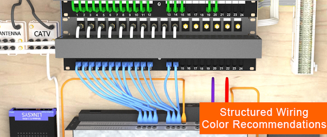
Color coding your structured wiring can make it easier to install and maintain. It can also help mishaps like having a contractor cut into the wrong wire by mistake. Unfortunately theres no standard for structured wiring jacket colors so lets come up with our own residential structured wiring color guidelines. Structured Wiring Cable Color Convention Were going to separate our cabling into 2 types. Premise wiring and patch cords. Premise wiring is the wiring that runs throughout your home, mainly between your central distribution area and jacks. Patch cords are used to make connections between devices in your central distribution area such as connecting a port on your network patch panel to a port on your network switch. Cat5e ca bles are really the only cables that give you much of a choice when it comes to jacket colors. You can easily find them in blue, green, purple, orange, yellow, red, grey, white and black. I chose to not use grey, black and white because those are the only co

American Standard Dual Injection Flush Valves Review

Gambar
Tomorrow a new High Efficiency 1.28 gallon per flush toilet is going to be available for sale on HomeDepot.com from American Standard that features a Dual Injection Flush Valves which give it great flushing power. The Optum VorMax is the first toilet to feature this new flushing system. I installed one about 2 weeks ago and I wanted to let you guys know about it. Read more »

Replacing Capacitor In Ceiling Fan With Diagrams

Gambar
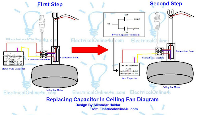
In this post you will learn about the replacing capacitor in ceiling fan . Ceiling fan numbering in those electric appliances and machines which we use very much in our life and mostly in summer season. In AC fan we have two types of internally winding which called main winding and starting winding. Most people know main winding with the name of running winding and starting winding as auxiliary winding. However in this post we only high lights the procedure of replacing capacitor in fan. Replacing Capacitor in Ceiling Fan Motor or other Fan Motor When your fan running slow or not running and make a type of sound then maybe your fan winding problem or capacitor but mostly this problem comes with capacitor. I also publish a post about role of capacitor in fan and you can learn by using the below link. Also read Role of capacito r in fan Ceiling fan capacitor connection diagram How to control speed of fan using speed control switch How to control speed and wire dimmer switch for ceilin

Digital Multi Voltmeter Ammeter Hz Wiring With Diagram

Gambar
Today i want to share a new digital meter which have multi option of measuring, by using this panel meter we can measure the voltage, ampere and frequency hertz and we dont need to wire extra voltmeter ammeter . We can also called this meter a advance type of panel meter. I also shown this meter images and its wiring diagram which is provided by company which i taken with my mobile camera. However the company diagram is not too hard and not completed thats why i design a diagram about this. How to wire a voltmeter ammeter and frequency meter with current transformer CT coil? The wiring of this panel meter is too simple, i want to show you an image of the this meter which is below. Voltage Ampere Hertz meter Now lets see the company diagram which is provided by company, the below is company diagram, you can also find out digital meter usage and auxiliary power supply table. digital meter company data and diagram We also wire current transformer (CT coil) with this for measuring ampere o

What is Normally Open Switch And How its Works

Gambar
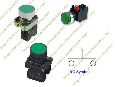
I published 2 post about power wiring / 3 phase wiring and in both post i talked about normally open switch and i used it in my diagrams. There will be many peoples how  dont know about that what is a normally open switch or what is NO push button switch and how its works. To make these question off, i am gonna to write this post and i  disuse only normally open switch in this post which we better known with his short name NO which mean normal open switch . However my next post will be about the Normally close switch or NC push button. What is Normally open switch and How its works This switch is momentary switch which is internally open electric circuit in normal state just like doorbell switch or we can said that doorbell switch is a good example of normal open switch. When ever we push this switch, it make contact of electric supply or make a close electric circuit. We can also called normally open contact switch. There are some images of normal open push button switch and its sy

Method of Wiring Lights in Series with diagram

Gambar
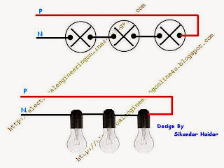
The wiring lights in series is best connection for better understanding for series circuit, form which a electrical student completely learn. Today in this post i am gonna to write about ,"how to wiring lights in series ". In this circuit i shall talk about voltage and current in series circuit. What is Series Circuit? The series circuit is a circuit in which we connect resistors in one line just like electric better cells. In series circuit current (Ampere) will be same in each part of circuit and voltage will be different. Another example of series circuit is a circuit where we plus resistors, for example we connect two 5 ohm ÃŽ© resistor then our complete resistance will be 10 ÃŽ©. OR, Series circuit is a circuit which have only one path form the source through all load, OR the series CKT is a circuit where have only way for completing circuit. Voltage And Ampere In Series Circuit : In series circuit the voltage will be different in every point and current (Amps) will b

Refrigerator Fridge Thermostat Wiring Diagram Guide

Gambar
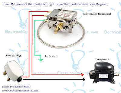
In this post you will learn about the fridge thermostat wiring diagram and instillation, as you know that we use refrigerator in our daily life, in refrigerator / fridge we have knob switch which is a movable switch from which we can control the coldness. We can easily make colder or cool from this knob. This is called thermostat switch and in this post you will learn about thermostat wiirng connection complete gudie which is a very simple connection. This connection is done in every refrigerator and air conditioner , There are different types of thermostat switches regarding wiring connection and regarding temperature. The working of thermostat in refrigerator / fridge or air conditioner is that switch off the compressor when the machines complete the coiling range. Fridge Thermostat Wiring Diagram - Fridge The rmostat Connection In Thermostat switch we have two types of connection, in which one is for main and other for out going to compressor, in some thermostat switches we have

Lock Back Utility Knives are Stupid

Gambar
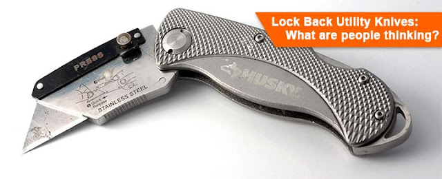
Over the past few years lock back utility knives have been gaining in popularity.They look cool because they look like pocket knives but I just dont find them as easy to use or as safe as traditional retracting utility knives. Most guys had pocket knives since they were kids. At least I know I did. Locking pocket knives are great because they keep the blade locked open so it doesnt accidentally close on your fingers. But you dont use utility knives like you do pocket knives. When I first saw them I thought they looked cool too and bought one but its not the first utility knife I grab when I have a choice. Just think of how you normally use a utility knife. Youre working on a project, maybe hanging or repairing drywall, trimming edge banding, cutting boxes for recycling, etc. In the middle of doing that, you need to cut something so you reach in your pocket or tool belt, pull out your utility knife, slide the blade up, make your cut, slide the blade back then put the knife away where

What is is Auxiliary Contacts and its working in Contactor

Gambar
In Electrical Power wiring we use different types of relays and contactor / motor starters and these have some contacts which we know with names of main contacts and coil contacts but this is not end we have also other contacts which we known with name of auxiliary contact . These contacts are available in every contactor but these auxiliary contacts in different types just lick Normally close and normally open which can set or fit on the contact or / motor stater and person can use it for different types of works. But the r eason of this post to learn that what is auxiliary contacts and what is the work of auxiliary contacts on a motor starter. So lets start it step by step. What is Auxiliary Contact and A Contacts on Contactor? Auxiliary means helper or we can said these are helper contacts in magnetic contact or relay which help us to done our work easily. And one thing more with out these contacts we can not control any thing by using magnetic cont actor . So these are

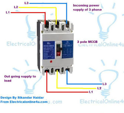
3 Pole 4 Pole MCCB Wiring Diagrams and Instillation

Gambar
As you know that there are different types of circuit breaker , in those circuit breaker a well known name is mccb which molded case circuit breaker and in this post you will learn about the mccb wiring and initiation. in this post i am gonna to share with you two diagram of mccb in which one is about the wiring of 3 pole mccb circuit breaker and other one is about 4 pole circuit breaker. By using the the three pole circuit breaker we can control three phase power system and by using the four pole we can control 3 phase 4 wiring system. However i also share diagram about the wiring and instillation of MCB (miniature CB) and you can also read about those diagram and post by using the following links. Also read below How to wire 4 pole mcb how to wire 3 pole mcb how to wire a distribution board How to instill mcb breakers in home wiring How to wire Three Pole and 4 Pole MCCB circuit breakers The wiring of mccb and mcb circuit breaker is same, and its too simple but the difference between

5 Wire Ceiling Fan Capacitor Wiring Diagram

Gambar
In this post i am writing about the 5 wire ceiling fan capacitor wiring diagram , in my last post i written about the 3 wire capacitor diagram which we use for fan and can regulate speed by using speed controlling switch. Now in this you will learn about ceiling fan 5 wire capacitor and its diagram. 5 Wire Ceiling Fan Capacitor Wiring Diagram In ceiling fan we use the 5 wire capacitor for speeds, low Med and High speed. On this type of capacitor we have five wire in which two is common and 3 other for different value capacitance micro farad. In the below diagram i shown a 5 wire fan motor capacitor with it;s capacitor diagram. In the above diagram i shown an image of fan motor capacitor which CBB61 and its a 5 wire capacitor, the two gray wire are common and red is 4.5 uF 250V and Brown is 6 uF 250 Volts and Purple is 5 micro farad and 250 V. Ceiling Fan 5 wire Capacitor Working and instillation Diagram for Fan regulating Speed Low, Med, High Also read 3 wire ceiling fan capacitor wiri